
 Figure 1This may come as a shock — coming from the author of the Subwoofer Array Designer — but over the years I have grown an increasing dislike for horizontal subwoofer arrays.
The only thing they really have got going for them, is their left‑to‑right spatial uniformity — provided — they do not fall victim to one honest mistake.
This article assumes that readers have a working knowledge of horizontal subwoofer arrays and are familiar with the usual reasons why audio professionals tend to deploy them.
Points of contention
My primary objection against horizontal subwoofer arrays is their lack of efficiency. Typically anywhere from ‑3 dB to as much as ‑9 dB (depending on the amount of delay tapering) whereby leaving precious SPL on the table.
Which can be recovered by doubling, or even tripling, loudspeaker‑quantity to make up for losses. But since every audio professional I encounter — tends to be a member of the "SPL Preservation Society" — yielding to such losses makes me wonder about double standards.
However, rather than efficiency, most audio professionals tend to object about horizontal subwoofer arrays' alleged time‑smearing. A concern I always feel is greatly exaggerated. And do not share for an array's — usable — frequency‑range when properly designed. Where it can easily be disproved by auditioning select third‑octave‑wide tone bursts.
Which begs the question: which frequencies are usable and which are not? Hold on to that question.
More double standards?
Ever since I entered this industry, I continue to be a firm proponent of equality for listeners. After all, if one pays the same price for an admission ticket, one could argue one is entitled to a similar experience. However, power‑alleys and ‑valleys (inherent to left/right subwoofer deployments) have become increasingly less of an issue to me.
If left/right subwoofers are somehow unacceptable, we should also have a conversation about left/right Main PA. With its unbeaten track‑record, having withstood the test of time for decades. Left/right Main PA's lower octaves — nowadays — are subject to the same issues, but seem to not cause anyone loosing any sleep over it. Which makes me wonder even more about double standards... Apologies, I digress. Back to the topic at hand.
Nobody contests whether or not horizontal subwoofer arrays ultimately suffer from artifacts in space, time, and frequency — most of which will be shown in this article — which is fine as long as these artifacts remain concealed and thereby inaudible. And therein lies the true culprit of our own making.
Designs based on electrical rather than acoustical crossover
Ask any audio professional for the maximum affordable spacing between subwoofers in a horizontal array (center‑to‑center) and you are likely to receive one of two answers: a) half or b) two‑thirds' wavelength of the "crossover" frequency...
Below crossover, that is — the usable frequency range — the array is expected to be well behaved. Whereas above crossover, it is not. And shit hits the fans (plural).
Where the most common misunderstanding I encounter in the field is: basing the subwoofer spacing on the — electrical — crossover, without taking into consideration the height of one's "Haystack".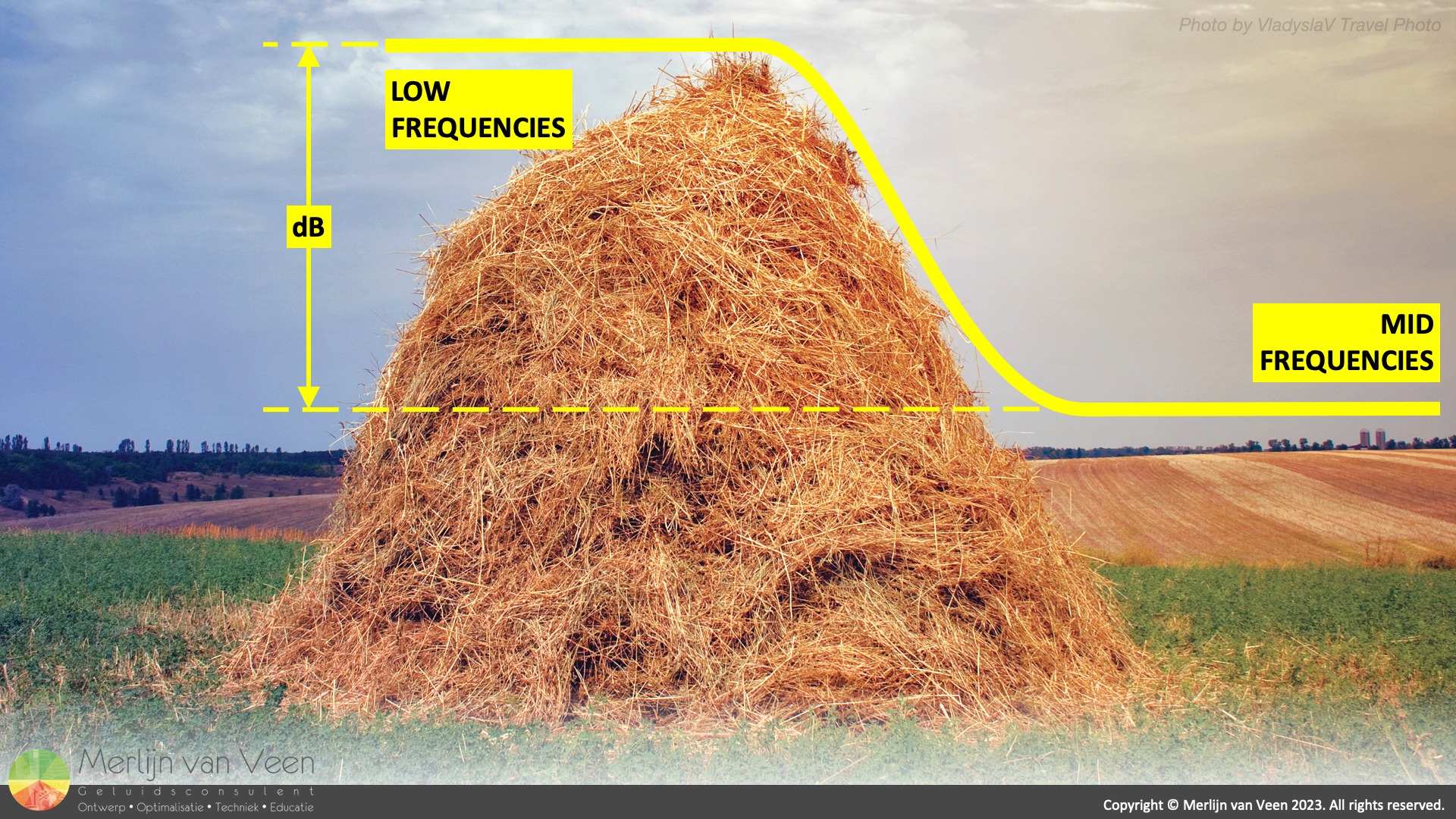 Figure 2The haystack (Figure 2) occurs when subwoofer‑level is increased above and beyond the mains' level, to emphasize low frequencies rather than extending them. Whereby introducing a shelf‑like elevation in the combined system‑response.
Erecting a haystack makes the — acoustical — crossover between Main PA and subwoofers, the frequency where both pass‑bands' — airborne — sound meet at the same level, wander up in frequency, and move away from the electrical crossover. Effectively broadening the subwoofers' pass band by audibilizing higher, otherwise concealed, out‑of‑band frequencies.
Failing to realize this, invariably results in a subwoofer spacing that is too wide. And raises our awareness of frequencies for which the array is neither designed nor optimized. Frequencies that are unambiguously subject to artifacts in space, time, and frequency. Let us dive in.
Beamwidth plots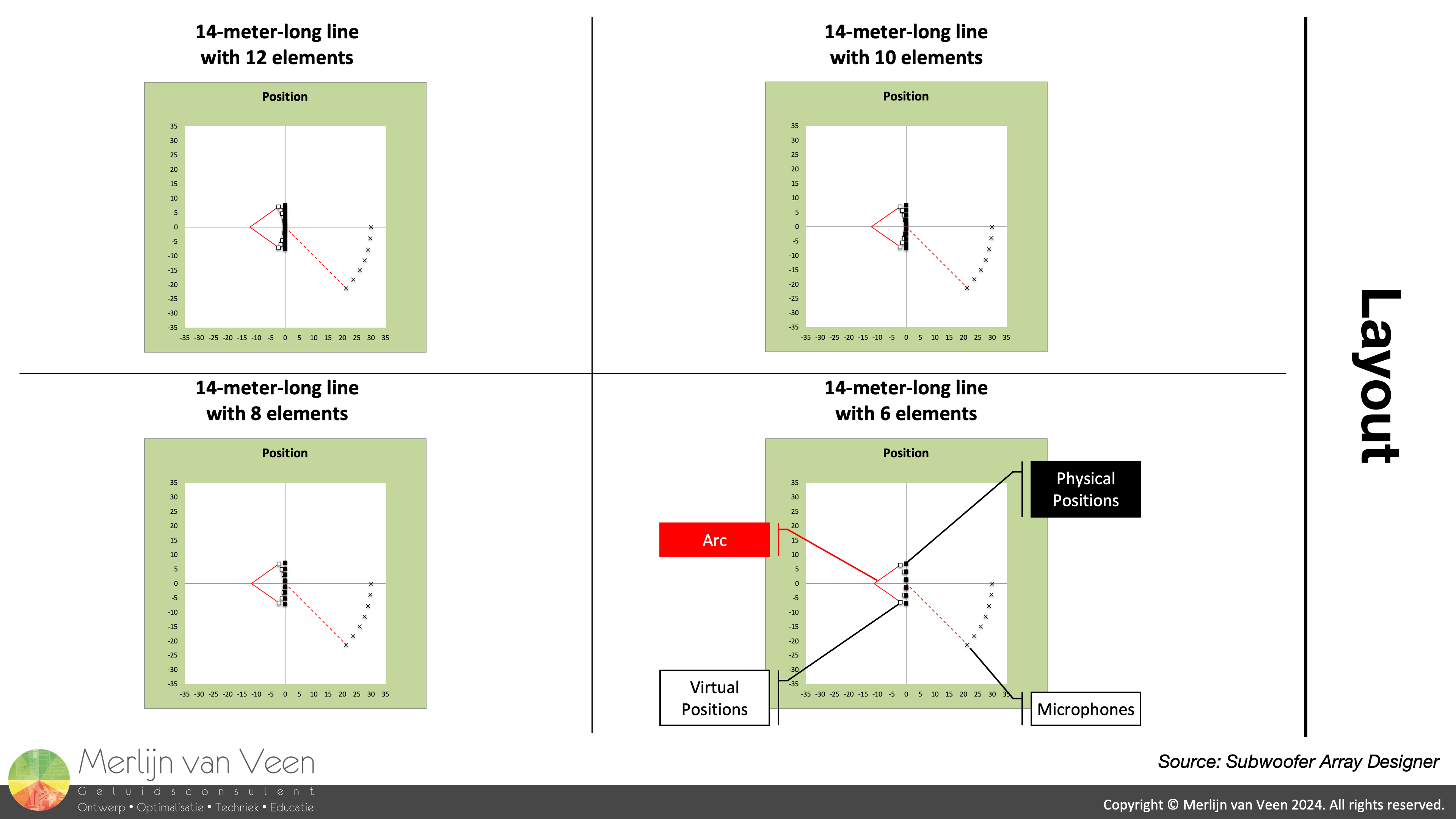 Figure 3
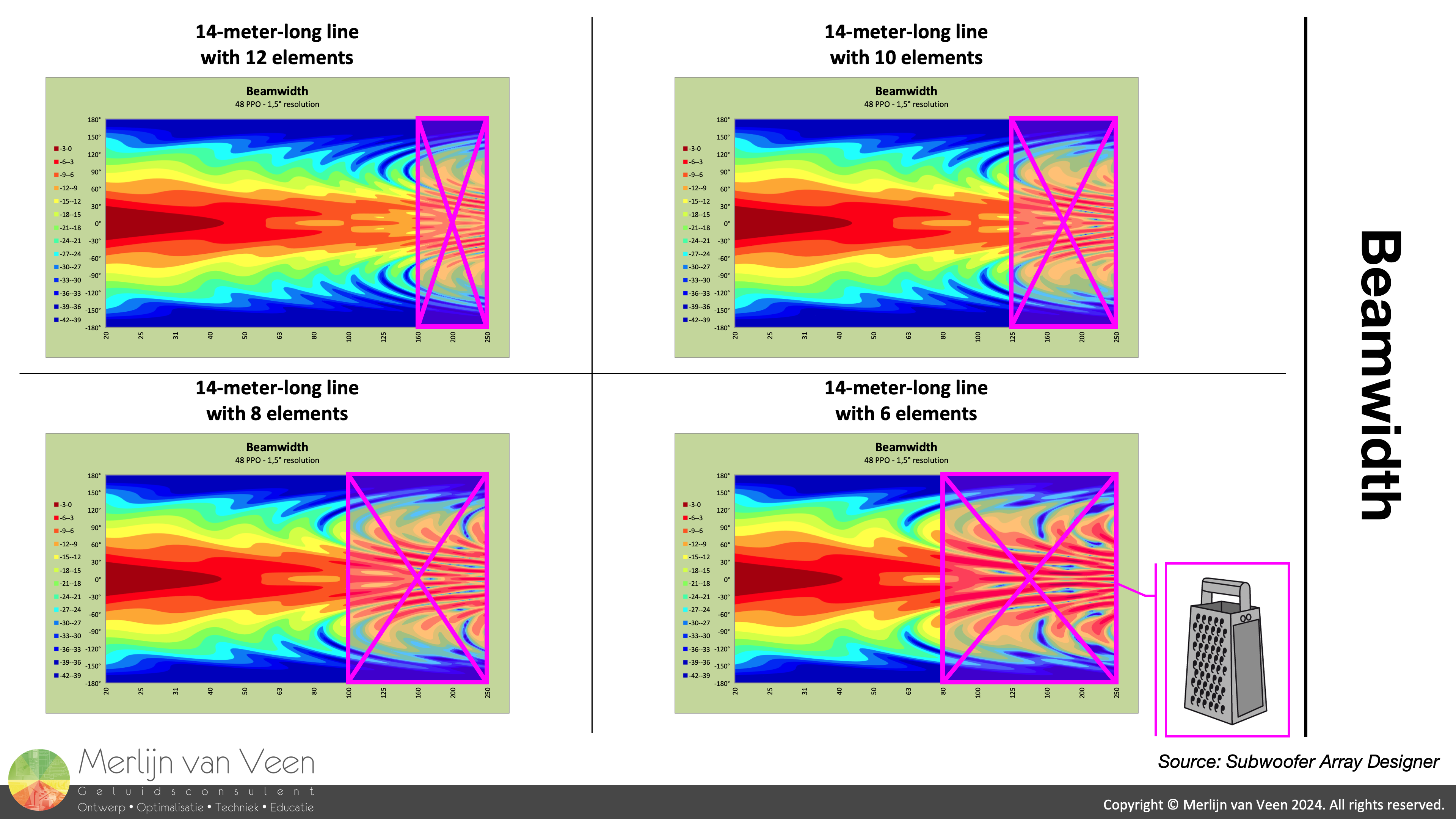
Figure 3 shows four designs in Subwoofer Array Designer. Where each subwoofer‑line is — equally long — but the number of elements is decreased from twelve to as little as six. In other words, the gap‑size increases, and loudspeaker‑density becomes sparser. In all cases, delay‑tapering has been optimized to yield a 90° spread.
Figure 1 (in the introduction) shows the beamwidth plot for each design. For frequencies whose half‑wavelength is equal or larger than the — center‑to‑center — spacing between elements, the array works as expected. With variance of less than 6 dB — throughout — the intended 90° coverage angle.
However, for the remaining — higher — frequencies, we observe what I have come to call: the "Cheese Grater". Notice the nulls (blue color denoting low levels) perforating the plot throughout this frequency span. Like someone used a die to punch holes into it. This aspect of the array — should — remain concealed and inaudible!
The arrays have not been designed and optimized for uniform coverage at these frequencies. Nobody likes this, including me.
Polar plots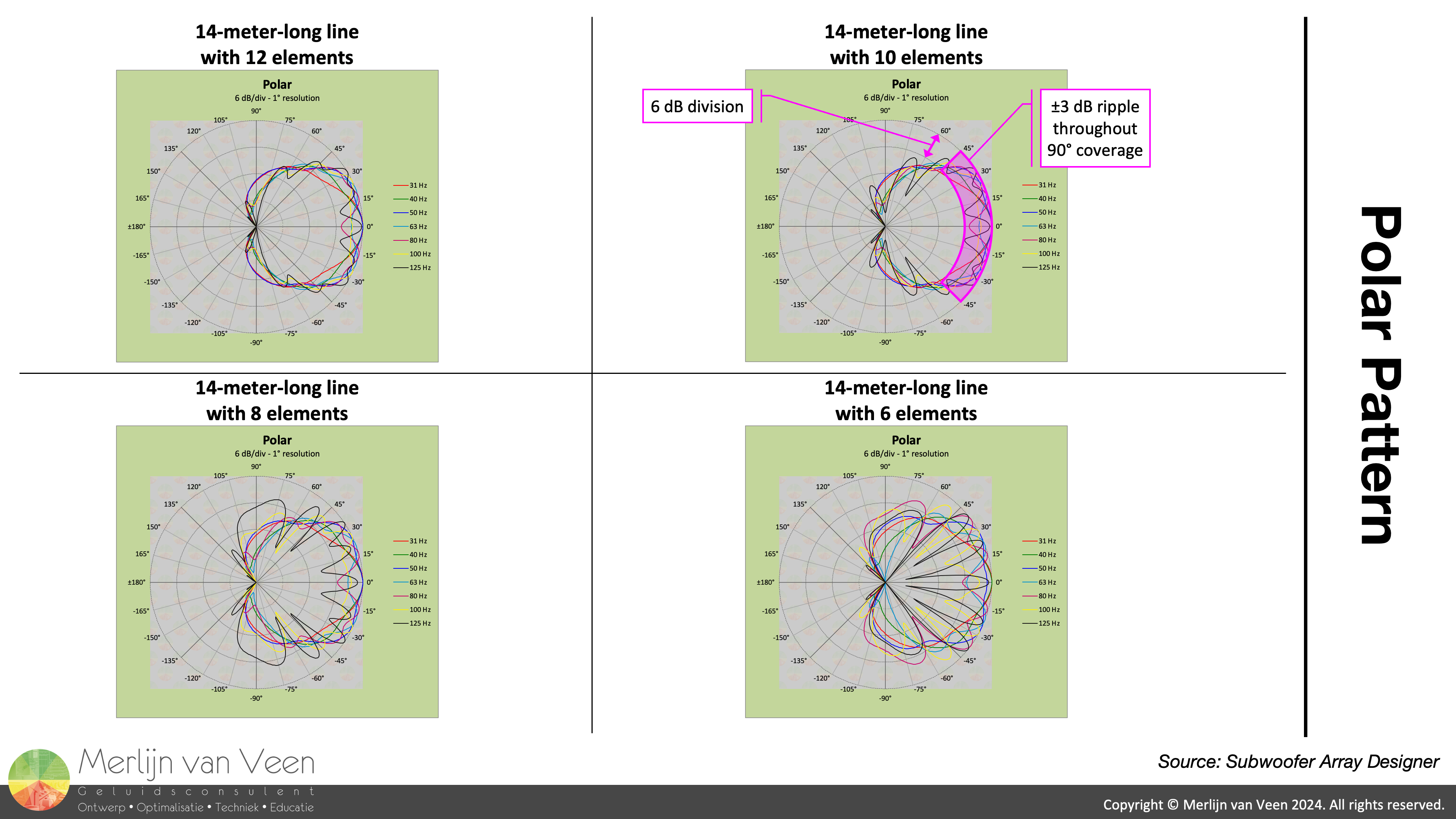 Figure 4Figure 4 shows more of the same, for select third‑octave frequencies.
When an array has been properly designed, its polar plot — for all frequencies of interest — exhibits at most 6 dB of ripple — within — its intended 90° coverage angle.
Notice that as array‑density becomes sparser, that is, wider spacing, the highest third‑octave frequencies are first to exhibit ripple in excess of 6 dB. Highly undesirable and therefore unusable.
Frequency responses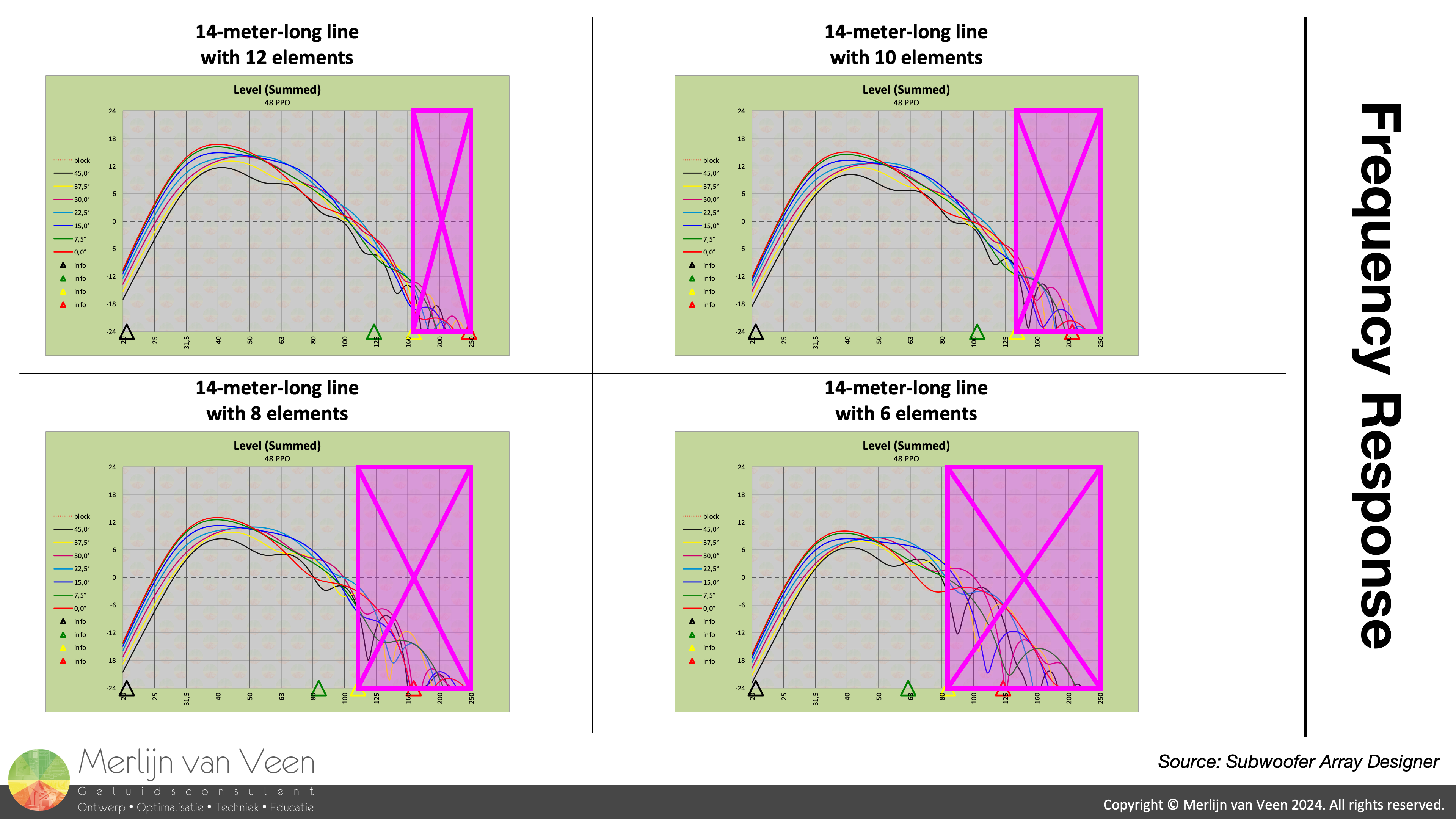 Figure 5Figure 5 shows — again — more of the same. All frequencies to the left of the green triangular marker on the frequency axis, which denotes half wavelength, for the seven microphones ranging — from 0° on‑axis to 45° off‑axis — exhibit 6 dB of variance or less.
Whereas all frequencies to the right of the yellow triangular marker on the frequency axis, which denotes two‑thirds' wavelength, exhibit ripple in excess of 6 dB, and are unusable.
Time domain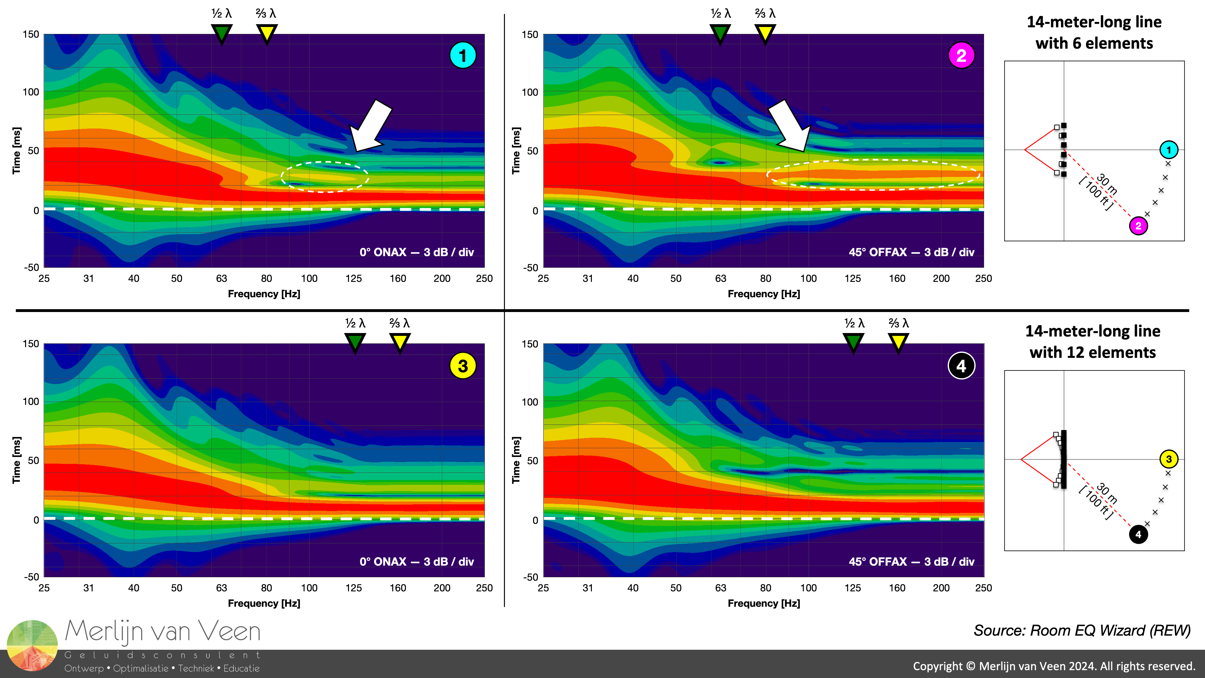 Figure 6The wavelet‑transform (Figure 6) clearly shows — significant — late‑arriving energy for frequencies where the spacing is too sparse (examples 1 and 2 in Figure 6). Most notably at the edge of coverage (example 2 in Figure 6).
These are the — out‑of‑range — frequencies that indeed are subject to time smearing whenever content is transient. Where time smearing progressively worsens from 0° on‑axis to 45° off‑axis.
For these frequencies, beamwidth plots (Figure 1) and both polar plots (Figure 4), as well as frequency responses (Figure 5), all exhibit ripple in excess of 6 dB .
Therefore, we do not want to hear this part of the spectrum — for which the array has not been designed and optimized — coming out of the subwoofers. Where Main PA should be — sole — custodian.
But what determines whether these ill‑behaved subwoofer frequencies remain concealed and inaudible? Spoiler alert... the height of your subwoofer haystack!
Relative levels matter
Ultimately, the acoustical crossover, which — you — set with your subwoofer level, determines which frequencies the audience hear coming out of the subs or the Main PA. Not the electrical crossover!
Now imagine that one designs an array, solely considering frequencies below the — electrical — crossover. For example, 63 Hz. And afterwards cranks up the subwoofer‑array's level to erect an 18‑dB‑tall haystack. Then everyone is made aware of all frequencies — for which the array is neither designed nor optimzed — and their undesirable artifacts in space, time, and frequency.
Where having the subs on an auxiliary is adding insult to injury. Cause now the size of one's haystack may change on a channel‑by‑channel basis.
Assume the worst
When I am asked to design a horizontal subwoofer array, the first thing I ask is: "How tall is your haystack gonna be?" Because this determines which frequencies the audience, as well as yourself, hear coming out of the subs or the Main PA. And once this question has been answered, I now know for which frequencies array‑performance needs to be artifact‑free. Which invariably results in an atypically small spacing.
If the client cannot answer this question, I will assume the worst. And err on the side of caution where I anticipate a taller rather than smaller haystack.
Self‑fulfilling prophecy
When it comes to horizontal subwoofer arrays, most audio professionals want to have have their cake — and — eat it too. That is, long lines (at least stage‑width) — and — wide coverage. And yet, anyone who knows their array‑theory is aware that, short lines are naturally wide and long lines are naturally narrow.
Meanwhile, the desire for long lines — with finite means — is conducive to large gaps. And inflates the spacing between subwoofers. Which in turn limits the array's usable — artifact‑free — frequency span. And without a significant haystack, that is, a low‑frequency — extension — rather than low‑frequency emphasis, this is perfectly acceptable. Where the very same un‑optimized frequencies are delivered by the Main PA instead. But this imposes a cap on the subwoofer level (relative to the mains).
However, whenever a haystack is desired — the rule rather than the exception — one should factor this into the design of the horizontal subwoofer array. Specifically the spacing between the elements.
Final notes
I have never been able to make a horizontal subwoofer array work with — less than 6 positions — regardless of how many elements are placed in each position.
I have never been able to successfully spread a horizontal subwoofer array beyond 120° (almost a perfect square) without tearing it apart.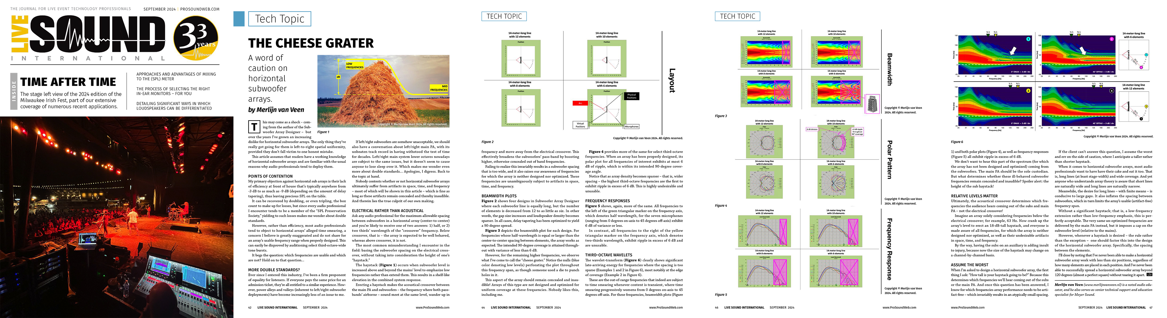
This article is also featured in the September 2024 issue of Live Sound International magazine.